

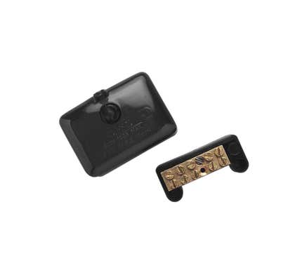
Meter Link
Brand Name: Clipsal
Type: Neutral
Range: Blue Point Series
Conductor Size: 35 sq-mm
Voltage: 500 V
Material: Brass
Color: Black
Connection Type: Screw
Current: 140 A
Number of Tunnels: 10
Dimensions: 108 mm x 62 mm x 55 mm
Mounting Center: 59 - 67 mm
Clipsal Link Neutral 10 Hole Suit 35Mm2 Cable - L10/35
Clipsal L10/35 Link Neutral 10 Hole Suit 35Mm2 Cable
Dispatch. 2 days
Need more?
This item is currently available for backorder with an estimated arrival time of 2 days
Please note this ETA is provided to us by our suppliers and could potentially be delayed due to factors outside our control. If there are any delays we will contact you to keep you updated.
Price
$37.62 $34.20
Choose your style, Select your Switch and Checkout
We can customise your powerpoint to a range of colours and layouts, suited to your needs.
Clipsal Link Neutral 10 Hole Suit 35Mm2 Cable - L10/35

Width 65
Height 56
Depth 111
| SKU | CLIL10/35 |
|---|---|
| Supplier No | L10/35 |
| EAN / Barcode | 9318793005364 |
| Width | 65 |
| Height | 56.000000 |
| Length | 111.000000 |
| Width | 65.000000 |
| Brand | Clipsal |
| Range | Max4 |
| Voltage | 500 V |
| Material | Brass |
Get Max 4 your buck
Complete protection with high performance. With Clipsal Max 4 you will find a range of enclosures, switchboards, residual current devices, miniature circuit breakers, isolators, distribution boards, overvoltage protection and accessories.
0 of 0 Reviews
A FEW FAQS
Yes the part number is L10/35R
3 x 9mm diameter to suit 35mm2 and 7 tunnels at 6mm to suit 16mm2
The part numbers are L11/25 for the neutral link and L11/25R for the active link.
Issue: How to install and connect the battery in a APC Power Conditioner with Battery Back-Up at first time start-up or following routine battery replacement. Product Line: APC AV Power Conditioners with Battery Back-UP S20BLK S15BLK S10BLK J15BLK J10BLK Environment: All models and serial number ranges. Cause: Battery must be installed and connected for proper device protection during power outages and interruptions. This is most common upon initial set-up or following a routine replacement of an end-of-life battery. Resolution: In accordance with APC’s interpretation of U.S. Department of Transportation regulations, APC ships this device with the internal battery pack disconnected. The front bezel of the unit is also not attached to the unit when shipped. This procedure provides for connection of the battery when the front bezel has been prematurely installed onto the chassis. Connect the internal battery pack as follows: 1. Grasp the front panel at the sides (Figure 4), and pull the front bezel from the unit. 2. Push the Battery Wire Connector (Figure 5) into the hole located at the left of the Battery Pack. Ensure that the Battery Wire Connector is pushed into the hole and securely connected by gently pulling on the wire to see if it is attached to the connector. 3. Install the battery retaining bar. 4. Install the front Bezel (Figure 6), by aligning the four pins located on the back-side of the Bezel to the holes at the left and right sides of the unit. Gently push the front Bezel onto the unit.