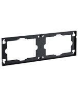
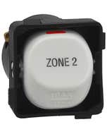
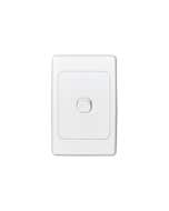
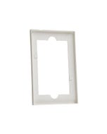
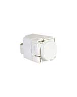
Clipsal Saturn Series Cover Paint Protector - 4000PP-TR
This item is currently available for backorder with an estimated arrival time of 2 days
Please note this ETA is provided to us by our suppliers and could potentially be delayed due to factors outside our control. If there are any delays we will contact you to keep you updated.
Choose your style, Select your Switch and Checkout
We can customise your powerpoint to a range of colours and layouts, suited to your needs.
| SKU | CLI4000PPTR |
|---|---|
| Supplier No | 4000PP-TR |
| EAN / Barcode | 9311554684075 |
| Product Type | Skin Only |
| Height | 24.000000 |
| Length | 115.000000 |
| Width | 75.000000 |
| Brand | Clipsal |
| Colour | Transparent |
| Orientation | Horizontal/Vertical |
| Range | Saturn Series |
Clipsal Saturn Series
The Clipsal Saturn range offers a sleek and modern design for any home or office. With a wide variety of blue LED pushbutton switches, power outlets, and mechanisms to choose from, you can easily find the perfect fit for your space.
There is also the option of updating or changing your Saturn look by purchasing Switch covers or Switch Grid and plates as well as power point covers plates. These products are made from durable materials and are easy to install, making them a great choice for both new construction and renovation projects. Buy the full Clipsal Saturn range online from Direct Wholesale
A FEW FAQS
Yes, the 4000PP will cover bother ranges. For more information, please refer to the link: https://www.clipsal.com/Trade/Products/ProductDetail?catno=4000PP
4000PP-TR ( sold as a pack of 250)
No, unfortunately you will need to use a C2000PP paint protector. For further information please visit www.clipsal.com/Trade/Products/ProductDetail?catno=C2000PP
The following network scales data from 0-4095 to 6400 - 32,000 when 4-20ma (6400 = 4 mA, 32,000 = 20 mA) outputs are required but a 0-20ma analog output is used. . Register 400001 and 400002 are used together in the top node of the EMTH Block, where 400001 is always 0000 data and 400002 is the variable data, 0-4095, to be scaled. Register 400003, displayed in data format float, is a fixed floating point value that the user enters as 6.25153 (note that two registers are used to create the floating point value, 400003 & 400004 in this example). Register 400005 (and 400006) is the floating point result of the integer and floating point multiplication (EMTH block). The FTOI (Floating Point TO Integer) block converts the floating point result of registers 400005 and 400006 to an integer value in a single register 400007. The AD16 block adds the top node register 400007 to the middle node constant 6400 and places the result in register 400009. This register will then map to one of the analog outputs. The following data screens shows the input values of 0 and 4095 and there corresponding results.
Goals and Symptoms When performing Modbus read commands, it is important to apply the right starting register address in the read function. Otherwise, the wrong register will be accessed from the meter, giving unexpected data for the meter parameter being read. Meter is functioning as expected. The front panel values for voltages and currents are within expected ranges for the system being monitored. However, modbus read functions from a master station (e.g. a PLC) give values that do not correspond to the front panel values. Facts and Changes Modbus, modbus rtu, function read, modbus map, holding register, staring register, function 03, modbus read packet Causes and Fixes Cause One probable cause would be that, the modbus function read command is not pointing to the right registers. The modbus protocol requires an offset to be introduced in the starting register address when reading the slaves register. Resolution When reading the meter parameters, the Master must send the device a Read Holding Registers packet. This packet must specify a start register and the number of registers to read. When the function read is received, the slave responds with a packet containing the registers in the range defined in the read request. However, consider the 3710 Modbus map, which states that according to the MODBUS protocol, in response to a request for address 4xxxx, the master reads register xxxx-1 from the slave (3710). For example, a request for register 40011 returns register 10 from the slave. What does the above statement mean? Why is an offset required? Holding registers, by default, are defined the 4xxxx range, the first holding register staring at 40001. The starting register in the read packet is, on the other hand, numbered from zero. Hence, the start register zero automatically points to holding register 40001, starting register one points to holding register 40002, etc. The fact that the first holding register is 40001 and not 40000 explains the offset that needs to be introduced in the starting register number. Hence, considering the 3710 Modbus Map statement, if the Master needs to read register 40011, then the corresponding starting register that needs to be put in the read function would be 10 (0A hex) since register 40011 is the register 10 from the first holding register, 40001: 40001 > Start register 0 40002 > Start register 1 40003 > Start register 2 40004 > Start register 3 40005 > Start register 4 40006 > Start register 5 40007 > Start register 6 40008 > Start register 7 40009 > Start register 8 40010 > Start register 9 40011 > Start register 10 The Modbus Read Request Packet for a master reading 3 registers from a slave with unit ID 100 (64 Hex) and for starting register of 40011 should be: Slave ID Function Start Register (40011) # of Registers CRC Checksum 64 03 00 0A 00032C3C To summarize, when looking at a modbus map, the starting register number to be used in the read function: Start Register = Modbus Register 40001. Original article#12774 Public All content © 1992-2007 Schneider Electric Legacy KB System (APS) Data: RESL188799 V1.0, Originally authored by KBAdPM on 11/03/2007, Last Edited by KBAdPM on 11/03/2007 Related ranges: Modbus / JBus
The following network scales data from 0-32,000 to 0-4095 for use with analog signals. Register 300001 contains the analog input data (0-32,000). This data gets BLKM (Block Moved) to register 400002. Registers 400001 and 400002 are the top integer nodes of an EMTH (Divide Integer by Floating point) which is divided by registers 400003 and 400004 (display 400003 as data type float), the middle node registers that contain the floating point constant (7.814408). The floating point result is found in registers 400005 and 400006 that is then converted by the FTOI (Floating point TO Integer) Block to register 400007.


