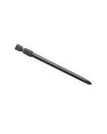
Self-Drilling Screw
Brand Name: Clipsal
Thread Size: 7 mm
Length: 30 mm
Drive Type: Phillips
Drive Size: #2
Point Type: Twin Start Needle
Head Type: Pan
Head Size: 8 mm Diameter
Clipsal Screw Self Drill 7Gx30Mm 100 Bag 357Ph30 - 357PH30
Clipsal 357PH30 Tek Screws, Pan Head, Needle Point Screws, Self Drilling, Yellow Zinc Plated, 7g x 30mm, 100 Pack
7 In Stock
Need more?
This item is currently not available for backorder.
We can notify you when it's available again by subscribing to the back in stock notification. Enter your email address and click submit to automatically receive an email when we get more in.
Price
$2.97 $2.70
Choose your style, Select your Switch and Checkout
We can customise your powerpoint to a range of colours and layouts, suited to your needs.
Clipsal Screw Self Drill 7Gx30Mm 100 Bag 357Ph30 - 357PH30


Width 1000
Height 300
Depth 1600
| SKU | CLI357PH30 |
|---|---|
| Supplier No | 357PH30 |
| EAN / Barcode | 9311554188801 |
| Width | 100 |
| Height | 300.000000 |
| Length | 1600.000000 |
| Width | 1000.000000 |
| Brand | Clipsal |
| Thread Size | 7 mm |
0 of 0 Reviews
A FEW FAQS
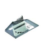
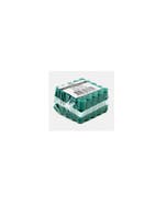
The part number for the bitsa box is 357TB. Some of the key features are: Tool boxes 12 compartment transparent box with assorted screws, screws and quantities included Includes: 357WF30 (100), 357/20 (150), 357WH12 (350), 357P30 (200), 357P20 (300), 357WH25 (100), 357PH50 (50), 357/63 (50), 357WHP32 (100), 357PH45 (100), 357/35 (100), 357/40 (100) For further information please visit www.clipsal.com/Trade/Products/ProductDetail?catno=357TB
357P20 is made of Zinc plated steel. For further information, please visit https://www.clipsal.com/Trade/Products/ProductDetail?catno=357P20
Issue: How is the cradle position indicated for NW breakers? Product Line: Circuit Breakers Environment: Masterpact NW Resolution: Cradle position is monitored mechanically and specific blocks on the top rail can be fitted with actuator mechanisms to indicate the 3 different states. The cradle comes standard with 3 each of the following; CD - indicates the disconnected position. This position is indicated when the required clearance for isolation of the power and auxiliary circuits is reached. CE - indicates the connected position. CT - indicates the test position. In this position, the power circuits are disconnected and the auxiliary circuits are connected. Specific contact blocks must be used in these positions, S33170 (push in type) or S48929 (ring terminal type). Instructions for adding/replacing here. These are the possible combinations available to provide cradle position status; Replacement part number of the actuators included with the cradle is S48560. Instructions here. More on Masterpact NW breakers here.
Issue While Installing SPM7.0.X and PME7.X the "Check 64 bit SQL Server" section of the installer fails. Product Line SPM7.0.X and PME7.X Environment Software Installation Cause SPM 7.0.X and PME7.X does not support the use of 32 bit versions of SQL Server 2008 on 64 bit Operating Systems. It is possible to install the 32 bit version of SQL Server 2008 on 64 bit OS/hardware. However if this is done, the Installer will not detect it as a valid SQL Server instance and you will see a screen something like this during the Check System portion of the Install: Resolution To correct this, you will need to install the 64 bit version of SQL Server 2008. Note that SPM 7.0 does support the use of 32 bit SQL Server 2008 on 32 bit Operating Systems. Additional Information It is possible to force the SPM 7.0 installer to allow a 32 bit version of SQL Server by manually editing broker.xml, but this configuration was not tested and is not supported. If there is some reason that this configuration is necessary, technical support, but be aware that if the software does not function as expected it will be up to the user to move to the officially supported configuration, that is, 64 bit operating systems require the 64 bit version of SQL Server 2008. Another reason that this problem could occur is if the selected SQL instance is using SQL Server 2008 Developer Edition. This is not a supported edition of SQL Server for production environments.
Issue: How to configure Logic Discrimination in Sepam Series 40 Product Line: Sepam Series 40 Environment: SFT2841 Resolution: How to configure the “Logic Discrimination” in SEPAM series 40, hardwire connection (I/O): First off it is clear that there are two relays. It could be named as downstream one (the one that sending blocking signal) and upstream one (the one that get the blocking signal). Please see the below diagram: Steps to config. downstream one: 1-It is a must to use I/O module, so select it in Sepam config. And physically it should be installed on Sepam 2-Next, you should enable the Logic discrimination option in Sepam parameter/ program logic. This step will put logic discrimination in service and also will assign dedicated output of the relay to send blocking signal to upstream. In Sepam series 40 it is assigned to output number 3 (O3). 3-Next, you need to set the protection functions both for logic discrimination and time-based discrimination according to your protection plan. 4-Last step is connecting O3 of downstream relay to one of the input (you are free to decide which input) in upstream relay. Steps to config. Upstream relay Steps 1, 2 and 3 should be followed the same way as for downstream. Step 4: chosen input (which is wired to O3 of downstream) should be assigned as “Blocking reception 1”. Here as an illustration we assigned I14 as reception of blocking = signal in upstream relay. *in S42 and S52 there is second “blocking reception”. For more information please check Sepam user manual. PCRED301006EN - 07/2012