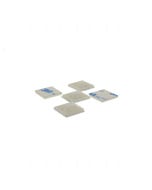
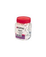
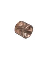
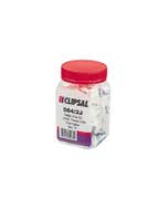
Conduit Saddle
Brand Name: Clipsal
Type: Half
Nominal Size: 40 mm
Length: 74 mm
Height: 41 mm
Width: 32 mm
Hole Size: 7 mm
Clipsal Saddle Conduit Half 40Mm H/Dip Galv - 180HD40
Clipsal 180HD40 Half Saddle, Conduit Clip, 40mm, HDG, Hot Dipped Galvanised
8 In Stock
Need more?
This item is currently available for backorder with an estimated arrival time of 2 days
Please note this ETA is provided to us by our suppliers and could potentially be delayed due to factors outside our control. If there are any delays we will contact you to keep you updated.
Price
$1.34 $1.22
Choose your style, Select your Switch and Checkout
We can customise your powerpoint to a range of colours and layouts, suited to your needs.
Clipsal Saddle Conduit Half 40Mm H/Dip Galv - 180HD40


Width 32
Height 39
Depth 76
| SKU | CLI180HD40 |
|---|---|
| Supplier No | 180HD40 |
| EAN / Barcode | 9311554038342 |
| Width | 32 |
| Height | 39.000000 |
| Length | 76.000000 |
| Width | 32.000000 |
| Brand | Clipsal |
| Nominal Size | 40mm |
| Hole Size | 7 mm |
0 of 0 Reviews
A FEW FAQS
Issue: Customer is installing the Conext SW and wants to confirm the wiring of the AC and DC cabling. Environment: Conext SW 2524 120/240 Split-phase (865-2524) Conext SW 4024 120/240 Split-phase (865-4024) Resolution: See the attached wiring diagrams for the Conext SW and Conext SW-NA. Do not mix AC and DC wiring in the same conduit or panel. Consult the applicable installation code for details. There are two dual 3/4" /1" trade-size knockouts on the side panel and another two on the bottom panel for AC wiring. Use the same trade size of strain relief as the trade size of the knockout(s) you are using.
Issue What is the difference between the SyMax Model 50 programmable controllers 8005CP50 and 8005CP51? Product Line SyMax Environment 8005CP50 Resolution The difference between the two SyMax Model 50 programmable controllers is the power voltage rating. 8005CP50 is a 120/240 VAC Processor Unit. 8005CP51 is a 24 VDC Processor Unit.
Issue: XW inverter charger will not qualify AC generator. AC IN light blinks AC input qualification, overloading the generator, unable to sustain battery charging and and running loads (multi-tasking) Environment: XW 4024/4548/6048 with AC generator Resolution: 1) Ensure generator is split phase 120/240, not 120 monophase or 120/208V. Voltage from (L1 to N) and (N to L2) should add up exactly to (L1 to L2) voltage 3) Recommended, size your generator 2 times the rating of the XW system. 2) Ensure no neutral to ground bond in Generator 3) Connect gen output to AC2, not AC1 and open up AC2 parameters in XW advanced settings - ac settings menu 4) Reduce max charge rate in XW 5) If Kohler RES series generator, see Solution 1179 Cause: 1) XW can only connect to splt-ph 120/240 unless converted to monophase 2) Potential ground loop 3) AC2 qualification parameter window much wider than AC1 4) Gen being overloaded by combination of house loads and XW charger.
Issue: Circuit breaker use at a lower system voltage Product Line: MCCB circuit breakers Cause: Circuit breakers are typically marked only with a few standard voltages, while other voltage systems exist. Resolution: Yes. According to 2011 NEC article 240.83(E), a circuit breaker may be used at voltages equal to or less than its' voltage rating. When applied on a system of lower voltage than marked, the interrupting rating is equal to the next highest marked interrupting rating. The only exceptions to application at less than rated voltage are: 1. QO and HOM -GFI, -EPD, -AFI, -CAFI, and DF circuit breakers must be applied on 120/240 Vac systems only (they need over 100 Vac to power the electronic modules) 2. EHB-EPD and EDB-EPD type breakers which must be applied on 480Y/277 systems only NOTE: Circuit breakers marked with DC ratings only are not suitable for application on AC systems, and circuit breakers marked with AC ratings only are not suitable for application on DC systems.
Issue: Implementing a hardwire stepdown transformer in a 208v or 240v environment Product Line: Smart-UPS / Symmetra Environment: APTF10KT01, APTF10KW01, and APTF20KW01, All Serial Numbers Cause: Unbalanced UPS outputs require a stepdown transformer to power 120v loads Resolution: This document refers to installing the APTF10KT01, APTF10KW01, and APTF20KW01 transformers in a North American 120/240 or 120/208 environment. For installations in other regions please consult the users manual. The wiring block outputs are as follows: For domestic use, make sure that the Terminal Block Jumper is installed between the Ground Terminal and Terminal 8 on the output wiring block, as illustrated on page 8 of the user manual. Please also make sure that the input voltage switch is in the correct position. The step-down transformer provides 240/120 output as 2 120v hots, a neutral, and a ground. It provides 208v output as a 120v hot, an 88v hot, and a ground. The 120v hot (terminal 7) and the 88v hot (terminal 9) are 180 degrees out of phase. You will measure 208v from terminals 7 to 9. The step-down transformer is not able to provide 2 120v hots that are 120 degrees out of phase as you would see with utility power. Note: If your installation requires both 208v and 120v output power you will need 2 separate subpanels: a 240v/120v panel and a dedicated 208v subpanel.
Issue: Lost Neutral - effects on loads and UL1449 Product Line: All Back-UPS, Back-UPS PRO and Personal Surge Environment: Lost Neutral in electrical infrastructure. Cause: Lifted neutral at utility panel. Resolution: In a typical balanced load with all loads using the neutral return and the neutral is severed, the voltage from each Phase appears across each load and is added on itself. This is a typical fault condition. Underwriter's Laboratories realized that this fault condition is common and it is not up to the Surge Protection Industry to prevent these failures but in the event of this common failure, UL addressed this condition by requiring all Surge Protectors to pass a fault of 240 VAC at different current levels to simulate different loads. These currents are: 125 mA rms. 500 mA rms. 2.5 A rms. and 5 A rms. They also require an unlimited current test (1000 A rms. or greater). 240 VAC is used because most household wiring is 120/240 3 wire single phase and a lost neutral produces 240 VAC. The unit during this test has cheesecloth wrapped around it. The unit may not emit flame nor can it char the cheesecloth nor can it create an opening in the housing that exposes live metal parts large enough for a child's finger to be inserted. After the test, the unit may not allow leakage currents of > 0.5 mA from Line to Ground and Neutral to Ground also it must withstand a dielectric voltage of 240 VAC for minute between each protected mode. Our units have passed this stringent test requirement in order to get UL recognition and to insure the safety of our customer's lives and property.