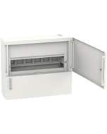
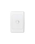
Clipsal CLIL5 Neutral Mini Meter Link with Cover
Clipsal L5 Link Neutral 5 Hole
6 In Stock
Need more?
This item is currently available for backorder with an estimated arrival time of 2 days
Please note this ETA is provided to us by our suppliers and could potentially be delayed due to factors outside our control. If there are any delays we will contact you to keep you updated.
Price
$12.19 $11.08
Choose your style, Select your Switch and Checkout
We can customise your powerpoint to a range of colours and layouts, suited to your needs.
Clipsal CLIL5 Neutral Mini Meter Link with Cover


Width 460
Height 510
Depth 650
| SKU | CLIL5 |
|---|---|
| Supplier No | L5 |
| EAN / Barcode | 9318793006262 |
| Width | 66 |
| Height | 510.000000 |
| Length | 650.000000 |
| Width | 460.000000 |
| Brand | Clipsal |
| Range | Max4 |
| Voltage | 500 V |
| Material | Brass |
Clipsal L5 Neutral Mini Meter Link 16 sq-mm 500V Black
Get Max 4 your buck
Complete protection with high performance. With Clipsal Max 4 you will find a range of enclosures, switchboards, residual current devices, miniature circuit breakers, isolators, distribution boards, overvoltage protection and accessories.
0 of 0 Reviews
A FEW FAQS
The hole sizes for the L5 & L7 neutral links are - 6.3mm & 5.8mm , these holes will accept up to 16mm cables For further information , visit link below:- https://www.clipsal.com/Trade/search-results?q=L5 https://www.clipsal.com/Trade/search-results?q=L7
The connector is an M8 4 pin female connector XZCPV0941L2 for a straight connector with PVC cable XZCPV1041L2 for an angled connector with PVC cable XZCP0941L2 for a straight connector with PUR cable for severe environments XZCPA0941L2 for a straight connector for food & beverage applications (change L2 to L5 or L10 for 5 or 10m cables) See attached data sheet
Issue: ATV320 setup for modbus control and terminals control via HOA switch. Product Line: ATV320 Environment: All Cause: LI1 will put the drive in terminal control and local wheel will be the speed reference. Resolution: LI1 FWD L5 is REf switch and CCS switch ref 1 modbus ref 2 is LCC Cd1 is modbus Cd2 is terminal control Profile is IO profile Jumper LI1 to LI5
Issue What is the proper procedure for installing a replacement power module in a single phase Symmetra UPS system? Product Line Symmetra Power Array Symmetra RM Symmetra LX Environment All serial ranges Cause This document discusses the recommended procedure for installing or replacing power modules in a single phase Symmetra UPS system. Resolution The following text describes the recommended procedure for use when replacing power modules. Please refer to the section that pertains to your particular model. Symmetra LX 1.) Remove the faulty power module. Identify the faulty power module using the display interface. The fault and diagnostic menu will identify any failed power modules by their location (L1 - L5). Remove the front cover of the UPS and locate the faulty power module. Power modules are installed on the left hand side of the system. The bays are labeled L1 - L5 (from top to bottom). Loosen the captive thumbscrew located an inch to the right of the power module's fan. When the screw is as loose as it can be, the latch that it is attached to should move down slightly to unlock the module. If the latch does not move down by itself, pull it down. Grab the handle and lift up on the module while pulling out. 2.) Install the replacement power module. Unpack the replacement power module from its packaging. Visually inspect the connector, located on the rear of the power module, for any signs of damage or nonconformance. If there is a problem with the replacement module, do not continue. Contact Schneider Electric technical support. Insert the replacement power module into the slot and slide it back until it is fully seated. Grip the thumbscrew, located just to the right of the power module's fan, and lift up on it to engage the latch. Hold the latch up and tighten the thumbscrew. The thumbscrew should be as tight as you can get it without the use of a tool. Confirm that the UPS recognizes the power module. The display interface should display a "Power module quantity increased" message. Ensure that there are no faults registered by the system. If so, contact Schneider Electric technical support. Re-install the front cover of the UPS. Symmetra RM 2-6 kva 1.) Remove the faulty power module. Identify the faulty power module using the display interface. The fault and diagnostic menu will identify any failed power modules by their location (L1 - L4). Remove the front bezels of the UPS and locate the faulty power module. Power modules are installed on the left hand side of the system. The bays are labeled L1 - L4 (from top to bottom). Loosen the two thumb screws in the upper corners of the module. Depress the black switch located on the right hand side of the front of the power module. While depressing the switch, grab the handle and pull the module out. 2.) Install the replacement power module. Unpack the replacement power module from its packaging. Visually inspect the connector, located on the rear of the power module, for any signs of damage or nonconformance. If there is a problem with the replacement module, do not continue. Contact Schneider Electric technical support. Insert the replacement power module into the slot and slide it back until it is fully seated. Tighten the thumb screws in the upper corners of the module. Confirm that the UPS recognizes the power module. The display interface should display a "Power module quantity increased" message. Ensure that there are no faults registered by the system. If so, contact Schneider Electric technical support. Re-install the front bezels of the UPS. Symmetra RM 8-12 kva 1.) Remove the faulty power module. Identify the faulty power module using the display interface. The fault and diagnostic menu will identify any failed power modules by their location (L1 - L4). Remove the front cover of the UPS and locate the faulty power module. Power modules are installed on the left hand side of the system. The bays are labeled L1 - L4 (from top to bottom). Loosen the captive thumbscrew located an inch to the right of the power module's fan. When the screw is as loose as it can be, pull down the black latch to unlock the module. Grab the handle and lift up on the module while pulling out. 2.) Install the replacement power module. Unpack the replacement power module from its packaging. Visually inspect the connector, located on the rear of the power module, for any signs of damage or nonconformance. If there is a problem with the replacement module, do not continue. Contact Schneider Electric technical support. Insert the replacement power module into the slot and slide it back until it is fully seated. Grip the black latch and lift up to engage the latch. Hold the latch up and tighten the thumbscrew. The thumbscrew should be as tight as you can get it without the use of a tool. Confirm that the UPS recognizes the power module. The display interface should display a "Power module quantity increased" message. Ensure that there are no faults registered by the system. If so, contact Schneider Electric technical support. Re-install the front cover of the UPS. Symmetra Power Array 1.) Remove the faulty power module. Identify the faulty power module using the display interface. The fault and diagnostic menu will identify any failed power modules by their location (L1 - L5). Remove the front bezels of the UPS and locate the faulty power module. Power modules are installed on the left hand side of the system. The bays are labeled L1 - L5 (from top to bottom). Loosen the screw on the latch that holds the power module in place. The latch is located near the bottom right corner on the front of the power module. When the screw is as loose as it can be, Pull the latch toward you and down into the frame. Grab the handle and lift up on the power module while pulling out. 2.) Install the replacement power module. Unpack the replacement power module from its packaging. Visually inspect the connector, located on the rear of the power module, for any signs of damage or nonconformance. If there is a problem with the replacement module, do not continue. Contact Schneider Electric technical support. Insert the replacement power module into the slot and slide it back until it is fully seated. Lift up the latch and push it into the power module until it stops. Hold the latch and tighten the screw. Confirm that the UPS recognizes the power module. The display interface should display a "Power module quantity increased" message. Ensure that there are no faults registered by the system. If so, contact Schneider Electric technical support. Re-install the front bezels of the UPS.
Issue Where can I find the answers to commonly asked questions about the Matrix UPS? Product Line Matrix UPS Environment All serial ranges Cause Some common questions may arise during the installation or use of a Matrix UPS. Resolution This document provides the answers to commonly asked questions regarding installation of the APC Matrix UPS. Installation Hints 1. Matrix-UPS should be set up on a solid level surface if possible. Padding on floor will help dampen system noise. 2. User needs to know input voltage to Matrix-UPS. If 240VAC input, Matrix-UPS Input Select Tap Wire must be moved. 3. Set Matrix-UPS EU (Electronics Unit, the top half of the unit) in place on top of Matrix-UPS IU (Isolation Unit, the bottom half of the unit) and tighten rear knob. 4. Add SmartCell battery packs to system, either on top of Matrix-UPS or by its side. 5. Hook Anderson connector from SmartCell battery pack to EU slot, then add SmartCell communications cable. Note: Battery communication cable must go from EU's "batt com" input to the "output" marking of first SmartCell. Follow this pattern for additional SmartCell battery packs. 6. Once all pieces are connected, turn main circuit breaker located on the rear of Matrix-UPS IU to "ON" position. 7. Front LCD display should read On-line with a % load. If LCD display does not illuminate, press all three buttons found directly underneath the display simultaneously. 8. User can then scroll through menu option of the LCD display to check current Matrix-UPS settings. 9. Change the sensitivity setting to LOW (default is AUTO). This LOW setting is preferred. 10. Go to menu "UPS Tests" and perform a battery test. Matrix-UPS Noises The Matrix-UPS will make certain noises which are normal to its operation and are acceptable. If the noise is not typical there will probably be other circumstances or errors along with the sound. Below are some of the acceptable sounds and their causes. 1. Loud Hum - This sound will be heard anytime the transformer is energizing (usually on startup) and is normal. The physical size of the transformer and the initial current surge into it causes this sound. 2. Beeping - The Matrix-UPS will make different beeps depending on the UPS condition or fault. Line Failure - four beeps about every five seconds Bypass - one beep every four seconds Bypass with no battery communication - five beeps Line failure with no battery communication - Continuous beeping Failed self test - Chirping 3. Clicking/Fineline Output Regulation This sound will be heard anytime the Matrix-UPS is adjusting taps for voltage regulation, the Matrix-UPS will maintain +/- 5 % on the output voltage. For the Matrix-UPS to switch taps, it will first go to battery and then the relays will adjust to the input line. To adjust for multiple switching, you can go to the menu, "UPS Setup", on the front LCD display of the Matrix-UPS Electronics Unit (EU, the top half of the unit) and change the setting from "Auto" to either "Low" or "Medium". a ) The Matrix-UPS features a tap changing regulator at the input with 6 taps. b ) Through proper selection of the input tap, the output voltage is maintained to within a narrow band; typically 5% of rated input voltage. c ) Intelligent tap changer adapts to varying line conditions from the front LCD display "UPS Setup" menu. d ) If any fault in the tap changer is detected the unit switches itself into bypass and displays "main relay fault" on the front LCD display. Matrix-UPS Certifications, Listings and Safety Agency Approvals UL listed, File # E95463: category YEDU - UPS Equipment, per UL 1778 CSA certified, File # LR63938: class 5311 05 - Power Supplies (Stand Alone), per standards C22.2 No 0, C22.2 No 0.4, C22.2 No 66, C22.2 No 107.1 TUV certified: per standards EN 60 950 and VDE 0558 (IEC 146-4) Novell Labs approved: NetWare compatible FCC verified: per FCC Rules Part 15, Class A Computing Devices EC verified: per EN50082-1, EN50091-1, EN55022 Class A VCCI Class 1: ITE Note: The Matrix-UPS is not UL1449 approved EMI / RFI The Matrix-UPS and SmartCell system were tested to withstand radiated electromagnetic (EM) fields per the test methods of IEC standard 801.3. The UPS withstands EM fields of 10 V/m over a frequency range of 10 kHZ to 150 kHZ, and 80% at 1 kHZ at 10 V/m over a frequency of 150 kHZ to 1 GHZ for both vertical and horizontal polarization. The Matrix-UPS meets the FCC Part 15 Class A computing device and CISPR 22 (EN 55022) Class A radiated emissions limits. Matrix-UPS Thermal Dissipation Matrix-UPS 3000 Matrix-UPS 5000 On-Line 540 BTU/hr On-Line 900 BTU/hr On-Line/Charging 900BTU/hr On-Line/Charging 1260 BTU/hr On-Battery 2000 BTU/hr On-Battery 3700 BTU/hr Matrix-UPS Overload Rating When the Matrix-UPS is on-line and overloaded, the input circuit breaker clearing times below can be expected. Overload Min. Time Max. Time 200% 10 sec. 100 sec. 500% 1 sec. 10 sec. 1000% 6 msec. 2 sec. 1200% 5 msec. 1 sec. If the overload continues for this amount of time the breaker will trip forcing the Matrix-UPS to battery. When the Matrix-UPS is on battery the inverter senses the overload and if it exceeds 100% of the UPS rated load, the UPS will shutdown within 4 seconds. Matrix-UPS Input Voltage The Matrix-UPS 3000 and 5000 models are wired from the factory for 208 VAC input. This can be verified a couple of ways once the unit is installed. 1 ) Go to the front display of the Matrix-UPS and scroll through to the menu "UPS Status" to check the input line voltage, in some cases this value may be varying and not exactly at either 208 or 240 VAC. 2 ) From the diagnostics menu you can view the UPS FW REV, this screen will show the internal micro revision of the Matrix-UPS which will be followed by either a letter "I" or a letter "M". If the select tap is wired default 208 VAC the letter "M" will be displayed, and the input voltage should be 208 VAC. If the letter "I" is displayed, the unit should be wired 240 VAC and the Input Voltage Select tap wire has been moved for that setting. 3 ) If the user inputs 240 VAC but did not move the Input Voltage Select wire, the letter "M" will show under UPS FW REV. The Matrix-UPS will show a fault or stay on battery. If the UPS Control menu selections are TURN UPS OFF and COLD START UPS, check the input voltage and circuit breaker. The UPS is not seeing any input voltage. Matrix-UPS De rating The Matrix-UPS 5 kVA is rated to work with a 30 Amp electrical service. Due to National Electrical Code (NEC) and Underwriters Laboratory (UL) restrictions, the maximum current drawn from such a service should not exceed 80% of the rated service, at nominal voltage. This limits the maximum current that the UPS can draw from a 30 Amp utility outlet to 24 Amps. With 240 VAC input, the unit is allowed to draw up to 5760 VA, so it can support a 5 kVA load even after allowing for small losses inside the unit. With 208 VAC input however, the unit can only draw a maximum of 4992 VA, and after accounting for the losses (< 7%), the UPS can only supply 4700 VA to the load in order to stay within the 24 Amps limit from the utility outlet. Matrix-UPS Transfer Time 1 ) Matrix-UPS transfer times to and from bypass: The transfer times to the bypass mode of operation differs depending upon how the Matrix-UPS is commanded to go to bypass. The transfer time out of bypass is always the same regardless of how it is done. To Bypass - Commanded via the front panel display or software, 1 ms typical - Rear panel bypass switch, 4 ms typical - Loosening the Electronics unit separating screw - 4 ms typical, 10 ms max. From Bypass - Via front display or rear panel switch - 0 ms typical Note that all types of UPSs exhibit a transfer time in going to bypass. Most on-line UPSs with bypass exhibit up to 8 ms of transfer time. It should be noted that this specification is usually unstated by the manufacturer. 2 ) How does the Matrix-UPS achieve a zero transfer time: The Matrix-UPS provides no-break, zero transfer backup power for protected computer loads. This performance is achieved by a combination of the following elements: Filter Isolates power failure from the load: The filtering elements in the Matrix-UPS, including the isolation transformer serve to isolate power faults from the protected load. Therefore, even if the input AC instantly falls to zero voltage, the output voltage is not affected for awhile due to filtering action. High speed power fault detection: Power faults are detected by a high speed microprocessor in less than 200 microseconds. As soon as a fault is detected the power flow of the inverter is reversed so that it supplies the load from the battery, which happens in about 50 microseconds. During this brief time, the filter has isolated the load from any disturbance, giving the detector time to operate. Input fault disconnection: A high speed switch made up of solid state devices and a rugged electrodynamics (relay) components quickly disconnects the input power when the inverter begins to supply battery power to the load. This is necessary so that the UPS does not feed any power back into the downed utility line, and prevents the utility line from loading the inverter if the utility line is a low impedance state. Inverter is already on-line: The power inverter converts battery power to AC is already connected to the output at all times due to the line interactive topology. This inverter is already operating before the power failure, but is controlled at that time so that power is flowing into the battery (battery charging). This means that no transfer or other switches are necessary to connect the inverter to the load when the power fails. The line interactive design of the Matrix-UPS does have power fault and corrections systems that take time to operate, but these brief delay times do not create a transfer time because the inverter is already on line and ready and the isolation filter in the UPS delays the power problem from reaching the output long enough to allow the inverter to reverse power flow and disconnect the input fault. Matrix-UPS vs. Ferro resonant UPS The Ferro resonant UPS (or FerrUPS) is not only limited in its manageability but also very inflexible when changing platforms. Matrix-UPS supports multiple loads in parallel. When multiple loads are powered on at different times, the FerrUPS risks dropping the load, while the Matrix-UPS will maintain stability. Efficiency with FerrUPS: At full load, the FerrUPS runs at 80% efficiency, compared to the 93% efficiency at full load for the Matrix-UPS. Fully loading a FerrUPS is dangerous due to the fact that Ferro resonant UPSs cannot handle a high inrush current. The FerrUPS must be de rated up to 50% to account for inrush current. As the load is reduced, the FerrUPS efficiency drops much faster than the Matrix-UPS. At 60% load, a Ferro resonant based UPS can have an efficiency as low as 65 to 70%, compared to a 90% efficiency at 60% load for the Matrix-UPS. Compared to the isolation transformer, ferroresonant transformers are heavy, emit much heat, noisy, and large in size. Also, the ferro's tank circuit must see a constant flow of 60 Hz power, plus or minus a fraction of a Hertz. Since this is a tuned circuit at 60 Hz, minor variations in source power frequency may cause the transformer's magnetic field to collapse. This is very important when on-site generation of power is used like a generator. Matrix-UPS Efficiency Matrix-UPS 3000 Matrix-UPS 5000 25% load > 84% 25% load > 82% 50% load > 90% 50% load > 89% 75% load > 91% 75% load > 91% 100% load > 92% 100% load > 93% Matrix-UPS - "W" & "J" Options Japanese Model The Japanese Matrix-UPS requires an input voltage of either 200 VAC or 208 VAC. The output voltage can either be 100/200 VAC or 120/208/240 VAC as selected by the VSS (Voltage Selection Switch). This switch is located on top rear of the Matrix-UPS "J" IU and can be adjusted by using a flat blade screwdriver. The output receptacles on the Matrix-UPS "J" IU are similar to that of the domestic Matrix-UPS, with the addition of an L11-30R twist-lock receptacle which provides voltages of 200 VAC or 208 VAC as selected by the VSS. The unit is almost identical to the domestic Matrix-UPS and the differences are in the IU. Worldwide Model The Matrix-UPS "W" (worldwide) has the ability to operate on a frequency of either 50 or 60HZ. The unit is almost identical to the domestic Matrix and the differences are in the IU. All EU's are interchangeable and can be used across the Matrix-UPS product line. Note: the MX5000J-EU can be used on a MX5000 worldwide or MX5000 domestic. Options The Matrix-UPS "W" (worldwide) has the ability to output 120 VAC by changing it's standard configuration. This is accomplished by either replacing the standard PDU with a domestic PDU plate ( X option-94 ) or by using the Matrix-UPS hardwire kit. APC Part Number Description MXA001 MX5000 Hardwire Plate MXA002 MX3000 Hardwire Plate MXA005 Meridian Alarm Cable Kit MXA006 Matrix casters MXA007 Matrix Rack Shelf MXA008 SmartCell Extender Cables MXA101 PDU - 10 5-15R, 1 L14-30R MXA102 PDU - 4 L6-20R MXA103 PDU - 8 5 - 20R MXA104 PDU - 4 L6-30R MXA105 PDU - 4 L5 - 30R MXA106 PDU - 4 L5 - 20R MXA107 PDU - 4 L6-15R, 4 6-15R, 1 L6-30R MXA108 PDU - 6 L5-15R, 2 L14-30R Harmonics Computers are non-linear loads that cause harmonics to flow in the power lines. Harmonics are currents that are multiples of the fundamental line frequency (50 or 60 HZ). The reason harmonics are a problem is due to two factors: Harmonics overload the neutral wiring in buildings and create a potential fire hazard. Harmonics overload building power transformers and cause them to wear out. Matrix-UPS helps reduce harmonics problems in the following ways: Matrix-UPS eliminates neutral currents: The Matrix-UPS does not use or need a neutral connection on its input. Matrix-UPS gets its input power from two single phase hot lines and a ground. The Matrix-UPS creates its own neutral and therefore all computers plugged into a Matrix-UPS do not contribute to the neutral current heating problem in anyway. Matrix-UPS reduces harmonics current in the hot wires: The Matrix-UPS reduces these currents in two ways. Matrix-UPS improves power factor and attenuates harmonic currents by about 20%. This reduces harmonic heating effects by about 36%. Galvanic Isolation Galvanic Isolation means that the output power circuit is electrically and physically isolated from the input power circuit. Electrical isolation is accomplished using an isolation transformer. Physical isolation means that the output power wiring does not touch or connect to the input wiring. All personal computers already have galvanic isolation between the input power and the computer logic built. This is a requirement of international safety agencies in order to prevent shock hazard. Many people mistakenly believe that galvanic isolation corrects noise on ground wiring. This is not correct. In fact, all galvanic isolation transformers only isolate the power wires, but pass the ground wire straight through. The actual affect of installing an isolation transformer is that common mode noise fed to the computer is greatly reduced. Matrix-UPS and Batteries: The Matrix-UPS has the ability to tell you many things about a user's site and often can provide the information needed to diagnose a problem right from it's own LCD display. Always ask questions that will characterize the situation even if at first they seem to have nothing to do with the reported problem. Compiling enough information around a problem will often help paint a picture of what is wrong when you cannot see it another way. Use the following suggestions when ever trying to diagnose a problem. This information can be read directly from the Matrix-UPS front LCD panel display. 1 ) Line Voltage 2 ) Output Voltage 3 ) % Load 4 ) Battery Voltage 5 ) Last Reason for Transfer 6 ) Battery Capacity 7 ) Number of Batteries 8 ) Number of Bad Batteries 9 ) Internal Temperature 10 ) Bypass Enable/Disable 11 ) UPS FW Rev The items in the above list may seem obvious but they play an important role in the diagnosis of the problem. From this data the next level of diagnosis can be performed such as checking to see if the transformer taps of the Matrix-UPS are changing or if the batteries are being charged. Using the information should help to quickly isolate which of the modules are having the problem.